Raymarine Autopilot
To many boat owners, an autopilot is an optional piece of equipment. But if you single hand your boat or if you must stand watch and steer the boat, especially in fog or darkness, and crowded harbors, an autopilot is a must have. There is no way you can steer the boat and hold a good heading while watching the radar, navigating with the chartplotter, and keeping an eye and ear to what's happening around you. The autopilot must be robust and reliable to handle poor sea conditions. Do not skimp when it comes to this piece of equipment.
There has been much discussion on the Yahoo Mainship list about which autopilot to use on the 400. I can't say one brand or model is better than another, but I can tell you what works.
My radar and chartplotter were Raymarine, so I chose Raymarine for the autopilot as well. I had Raymarine Wheel-Pilot in my Morgan sailboat and had a Sport-Pilot in my fishing boat, and I was happy with them both. I liked Raymarine's Seatalk interface and I thought it would be best to have all the electronics be of like brand for best compatibility. In retrospect, I did make the right decision.
The Raymarine autopilot has been the best piece of equipment I have installed on the boat. I use the autopilot as soon as I leave the dock and it runs till I return. It has never faltered. It is a far better helmsman that any person good be, in keeping the boat running true in all sea conditions. The system installed on Stella Blue is robust. It will handle yachts much larger that Stella Blue. A boat the size of Stella Blue, falls in the lower end of the recommended range of application for this system, thus resulting in a very responsive system while keeping the workload fairly light for the autopilot. Now for the details.
Raymarine manufactures 3 different hydraulic pumps for this class of autopilots, type 1, 2, and 3. The size pump you need is determined by the volume of the steering cylinder. The single engine 400 uses a 13.7 cu. in. (BA175-7TM) cylinder, with a 2.4 cu. in. (SeaStar II) pump. The Raymarine type 2 hydraulic pump covers applications from 9.8 – 21 cubic inch and this is the pump to get. (Even though the ram capacity of 13.7 falls within the type 1 pump (4.9–14 cubic inch rams) range, do not use the type 1 unless you always boat in flat water with no wind. It is marginal in capacity and will give unsatisfactory performance in this application)
The pump type determines the corepack that you will need. The corepack is the course computer and the power supply/controller to drive the pump. The corepacks come in two versions, with or without internal rate gyro. The rate gyro is a sensitive instrument that senses yaw much faster than the compass can supply heading information. If you want your boat to track straight in following seas, the rate gyro is a must. Stella Blue uses the 400G corepack that includes the internal rate gyro (this model name has been renamed the S3G.)
Finally, you will need control heads. I use the 8001 on the flybridge. It has a large display that makes it very easy to see, and a knob to dial in the heading or to steer with in power steering mode. It also has dedicated buttons for most functions so you do not need to remember to press combinations of keys simultaneously as some other control heads require.
Before I bought the autopilot, I inquired of several dealers about installation cost and mounting locations. Costs were estimated from $1500.00 on up, and the proposed installations were not at all what was recommended by Raymarine. I didn't like what I heard from any of them, so I decided to do it myself. A couple of them were going to put the system up on the flybridge, which is probably the easiest, but worst (furthest) location from the rudder. The installation is rather straight forward and took about a day.
Selecting a location
Raymarine suggests that the pump be located as close to the ram as possible. Nobody I talked to thought that was a good idea. First, it might be subject to salt water corrosion if green water leaked through the hatch seal above, and it would require another break point in the hydraulic lines. The next best location would be at the first junction of the lines where they meet below the lower helm station. Tapping in at this location would minimize plumbing, the pump would be in a dry controlled environment, and it would still be in a relatively low point of the hydraulic system to make bleeding less problematic.A suitable location under the stairs for the corepack and compass would be near by minimizing wire runs. It is a very serviceable location as well.

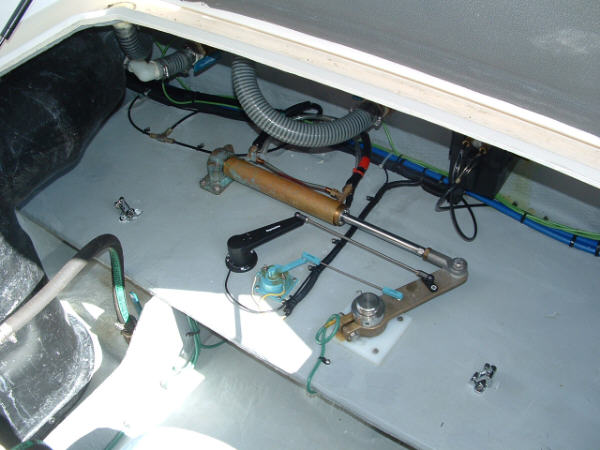
Before I started the installation, I had an aluminum bracket fabricated for some 1/2" thick 6061-T6 aluminum plate. Not knowing at the time, where the exact location of the pump would be I used a piece of 1/2" starboard to mount the bracket to the 2 x 4 beam behind the shower and just above the hot water heater. The junction where the lower helm, upper helm, and rudder lines all meet, is just a few inches above. I had three short hydraulic lines made up by Allied Industrial Products, in New Britain, CT, to patch the pump into this junction. Three more brass tees and some MPT / male compression adapters and the pump is all plumbed in!

The corepack is mounted just a few feet away under the stairs. Again, a well protected and serviceable location for the electronics. The power for the unit comes off the DC buss bars behind the air return screen located below the lower helm station. In the above picture you can see the red and yellow wires that feed the core pack bundled up with the red and black coming from the corepack to the pump.

In addition to the power in and power out to the pump wires, there is a rudder angle transducer, an electric compass, controls leads, and a wire to turn the unit on/off. The rudder angle transducer wire runs across the bulkhead and then aft along side the fuel tank to the aft compartment. It follows the trim pump and the analog rudder angle transducer wires. Not a very tough run. That whole mess is protected by a shelf I built as another project.
The leads to the flybridge control head follow in the same direction but then take a vertical run above the starboard fuel tank along with the rest of the flybridge control wiring and cables. There is a plastic cover held in place by three screws in the starboard flybridge seat storage compartment. There are (2) - 3 or 4 inch PVC pipes that all the wires, cables, and hoses run through. Just find the least crowded and run a wire messenger down the pipe to pull up the leads. Another long somewhat flexible stick or plastic rod, to carry the leads forward along the starboard side of the bridge will make life easier. The rest of the wires will be very easy to run behind the lower helm bulkhead for the on/off switch and lower station control head if used. I had a 600R portable head left from a previous boat that I wired for the lower station. It has enough cable where I can carry it out to the fore deck and steer from out there if I choose.

The electric compass should be mounted as close to the center of the boat in a lowest part of the boat to minimize the effect of roll and pitch and also be mounted as far as possible from large iron or magnetic objects. Mounting on the wall just below the support for the stairs satisfies all these criteria. It is also somewhat sheltered by the stair support. The compass heading is offset by the course computer setup, and it does not matter what relative direction the compass is aligned with on the boat. This location puts it far from the engine and the maximum deviation reported on calibration was 2 degrees in this location, which is quite good. The course computer will build its own deviation table to correct for this.

The last part of the installation is the on/off switch. The corepack uses a circuit between two terminals on the board to shut off the system. If the circuit is closed, the system is off and if the circuit is open the system is on, the reverse of what you might expect. So I found one of the switches at the lower helm that was unused and removed power from it by cutting the buss bar feeding that switch. I then ran the wires from the corepack to it and re-labeled the switch. Bleed the hydraulic system and then it was ready for sea-trial and calibration. Read the manual! It is easy, but must be done correctly.
We have had the pleasure of using this system for three years now with out a problem. I am always amazed and thankful for how well this system works. It really helps make piloting pleasurable in all but the worst conditions. There are many brands of autopilots out there, and they probably all do an adequate job if installed correctly, but I found the documentation, ease of installation, and performance of this system to be highly satisfactory.